
How to Test ESD Mat Resistance: Meter Setup and Pass Limits

How to Test ESD Mat Resistance: Meter Setup and Pass Limits
To test ESD mat resistance, use a surface-resistance meter and the correct electrode setup, isolate the mat from other conductive paths, and measure either resistance point-to-point (RTT) or resistance-to-ground (RTG/RTGP). Apply the test voltage specified by the relevant standard, ESD control program, or product TDS, then compare the reading with a limit from the same source — there is no single universal pass limit for ESD mats.
This guide covers ESD bench and work-surface mats. ESD flooring and footwear/flooring systems use different test methods and limits and are not covered here. The goal is a repeatable procedure: the right meter, the right electrode placement, the right voltage, and a defensible pass/fail decision.
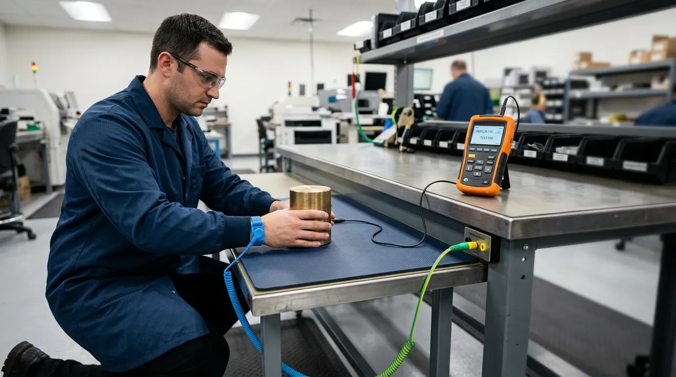
What ESD Mat Resistance Testing Measures — and What It Can't Prove
An ESD mat is a static-dissipative work surface. It controls static charge by providing a controlled path to ground through a grounding cord or groundable point. ESD mat resistance testing measures how easily charge moves on that path.
Surface Resistance vs Surface Resistivity: Why the Unit Matters
Surface resistance is the resistance between two electrodes on the same surface, expressed in ohms. Surface resistivity is a material property expressed in ohms per square. The two terms are related but not interchangeable. A meter reading in ohms is not a resistivity value.
If you need resistivity, use the test method and electrode geometry designed for it, such as the concentric-ring electrode arrangement in ANSI/ESD STM11.11. For a fuller explanation of the difference, see surface resistance vs surface resistivity esd.
What a Resistance Test Does Not Prove
A single resistance reading does not verify the whole ESD workstation. Specifically, it:
- Does not prove that the ground cord is connected to a verified facility ground.
- Does not verify that the wrist strap, ionizer, or other ESD controls are working.
- Does not measure triboelectric charge generation.
- Does not tell you whether the mat will pass a different measurement type or a different test voltage.
Broader ESD control programs, such as IEC 61340-5-1, require a wider set of technical and administrative controls than a mat resistance reading alone.
Equipment and Test Conditions
Use a surface-resistance meter or megohmmeter with an appropriate range for static-dissipative materials. A basic multimeter is not suitable for this kind of verification. The meter must be set up and operated according to its manual, and if the ESD program requires documented results, the meter must be within its calibration period.
Required Equipment Checklist
- Surface-resistance meter or megohmmeter with a suitable resistance range
- Two 5-pound electrodes for point-to-point testing
- Ground lead for resistance-to-ground testing
- Verified calibration status, if the result will be documented
- Approved cleaner and a clean, dry cloth or wipes
- Insulating layer, if the mat is installed on a metal bench
Preparing the Mat and Work Area
Clean the mat with the manufacturer's recommended method and allow it to dry completely. Dirt, flux, or moisture can change the reading. Remove any conductive items touching the mat that could create an unintended parallel path. If the mat sits on a metal surface, isolate it before testing so the meter measures the mat rather than the bench.
Also identify the mat's grounding method. A mat with a ground snap is tested differently from a mat connected to a common-point ground, so know the intended grounding point before choosing RTG or RTGP.
Choose the Right Measurement: RTT, RTG, or RTGP
Before placing the electrodes, decide what you are verifying. Resistance point-to-point looks at the mat surface itself. Resistance-to-ground looks at the path to the facility ground. Resistance-to-groundable point looks at the path to the mat's own ground snap or grounding point.
| Measurement | Meter connection | What it verifies |
|---|---|---|
| Point-to-point (RTT) | Two 5-pound electrodes on the same surface | Resistance across the mat surface |
| Resistance-to-ground (RTG) | One electrode on the surface, one lead to facility ground | Resistance from the surface to the building ground |
| Resistance-to-groundable point (RTGP) | One electrode on the surface, one lead to the mat's groundable point | Resistance from the surface to the mat's intended ground point |
Desco's meter guide describes the same distinction: two 5-pound electrodes for point-to-point resistance, and one electrode plus a ground lead for resistance-to-ground. Choose the measurement type before you record anything. A resistance result without the method is not a valid pass or fail.
Meter Setup and Test Voltage
Set the meter to the correct measurement mode and resistance range. Most surface-resistance meters used for ESD verification offer a 10 V setting, a 100 V setting, or automatic voltage selection.
Why Test Voltage Matters
Some static-dissipative materials produce different readings at different voltages. A 10 V reading is not automatically equal to a 100 V reading, so the result is only valid for the voltage you used. Follow the voltage requirement in the product TDS, the ESD control program, or the meter manual, and record the voltage with the result. Transforming Technologies' ESD Q&A explains why this distinction matters in practice.
Verifying Meter Calibration
If the result is being used for compliance, verify that the meter is within its calibration interval. Some ESD programs also require a verification check on a known resistance standard before testing. Record the meter identification and calibration status alongside the test result.
Electrode Placement and the Step-by-Step Test Procedure
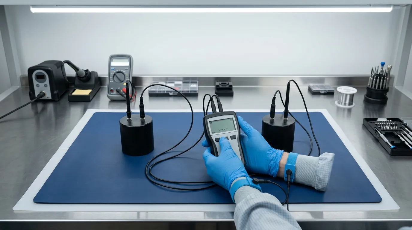
Electrode placement changes the measurement, so follow the meter manual or the test method rather than placing the electrodes wherever convenient.
Electrode Placement Rules
Keep the electrodes away from the mat edges and away from the grounding point unless the procedure says otherwise. Edge effects and the ground connection can alter the resistance path. The exact placement instructions should come from the meter manual or the test method in use, as Desco's meter guide describes. For an installed mat, resistance-to-ground is often measured from the center of the mat surface, as noted in Desco's mat installation guide.
Step-by-Step Test Procedure
- Isolate the mat. Remove anything conductive that touches the mat and is not part of the intended ground path.
- Clean and dry the surface. Use the manufacturer's approved cleaner and wait for the surface to dry completely.
- Connect the meter. For RTT, connect two electrodes. For RTG or RTGP, connect one electrode and the ground lead.
- Select the test voltage. Use the voltage required by the applicable standard, ESD control program, or product TDS.
- Place the electrodes on the mat surface at the distance specified by the meter manual or test method, away from edges and groundable points.
- Apply the test and read the meter. Record the reading in ohms.
- Record the complete test data. Include measurement type, voltage, electrode arrangement, location, date, operator, and meter ID.
Pass Limits: How to Judge Your Reading Correctly
There is no universal pass limit for ESD mat resistance. A reading only becomes a pass or fail when it is compared with a limit from the correct source.
Where Valid Pass Limits Come From
| Source | What it provides |
|---|---|
| Product TDS | Declared resistance range or classification for that product |
| Customer specification | Project-specific pass/fail requirement |
| ESD control program standard | System-level requirements, such as IEC 61340-5-1 |
| Meter manual | Operating instructions, not a pass limit |
ANSI/ESD STM11.11 defines a test method for measuring the surface resistance of planar materials, but it does not set one universal value for every mat. IEC 61340-5-1 defines broader ESD program requirements. The specific limit for a mat should come from the supplier's TDS or the customer's specification.
How to Record a Test Result
Record enough detail to make the result defensible:
- Measurement type: RTT, RTG, or RTGP
- Test voltage
- Resistance value in ohms
- Electrode arrangement
- Location on the mat
- Operator name
- Date
- Meter identification and calibration status
If the specification requires it, include temperature and humidity. A complete test record also makes troubleshooting easier later.
Troubleshooting a Failed Reading
A failed reading should not immediately condemn the mat. Work through the test setup first.
The Failure Checklist
- Confirm the measurement type. Comparing an RTT reading to an RTG limit is invalid.
- Repeat the isolation step. An unintended ground path can change the reading.
- Clean the surface again and let it dry. Contamination is a common cause of high readings.
- Inspect the ground snap, ground cord, and connection point.
- Check the meter battery, leads, and calibration status.
- Retest at the same location.
- If the mat still fails, keep the test record and contact the supplier.
Desco's surface-resistance test kit manual also recommends cleaning and retesting before treating the material as faulty.
Supplier Evidence: TDS vs Batch Test Report
A TDS is a specification sheet. It states the intended performance of the product. A batch test report contains measured data from a specific batch or sample. The difference matters when you are approving a mat or investigating a failure.
| Document | What it is | What it should include |
|---|---|---|
| TDS | Product specification | Intended resistance range or classification, test method reference |
| Batch test report | Measured data for a specific lot or sample | Method, voltage, electrode arrangement, conditions, result, date |
| Calibration certificate | Instrument accuracy record | Calibration date, due date, standard used |
Ask the supplier which measurement method was used, what voltage was applied, and whether the result applies to the batch you are actually buying. For Nabai's anti static mat products, confirm the specification on the product page rather than relying on a general brochure claim. The same applies to an esd anti static mat.
Quick Answers to Common ESD Mat Test Questions
Can I test an ESD mat with a multimeter?
No. A standard multimeter is not designed for the high resistance range of static-dissipative ESD mats. Use a surface-resistance meter or megohmmeter with the appropriate range for ESD verification.
Should I test at 10 V or 100 V?
Use the voltage required by the applicable standard, ESD control program, or product TDS. If none is specified, follow the meter manual and record the voltage with the result. A 10 V reading and a 100 V reading are not automatically comparable.
Is testing an ESD floor mat the same as testing a bench mat?
No. ESD floor mats are usually verified as part of a flooring or footwear system, which uses a different test setup. For more on the distinction, see anti static mats floor.
Testing an ESD mat correctly comes down to measuring the right property, using the right setup, and comparing the reading with a limit that actually applies. If you can record the measurement type, test voltage, electrode placement, and the source of the pass/fail limit, you can defend the result — and you will know exactly what documentation to request from the mat supplier.
NEWS
GET SERVICE
With quality parts to meet every budget and friendly staff trained to make your visit informative and hassle free.